
Box vertebra
The lower chord of each wall: 150 × 180 mm with 12 mm walls, 500 mm long, post-tensioned by steel strand. A bought steel box is the fallback if the thick iron does not qualify.

MSEC 50K · Main design
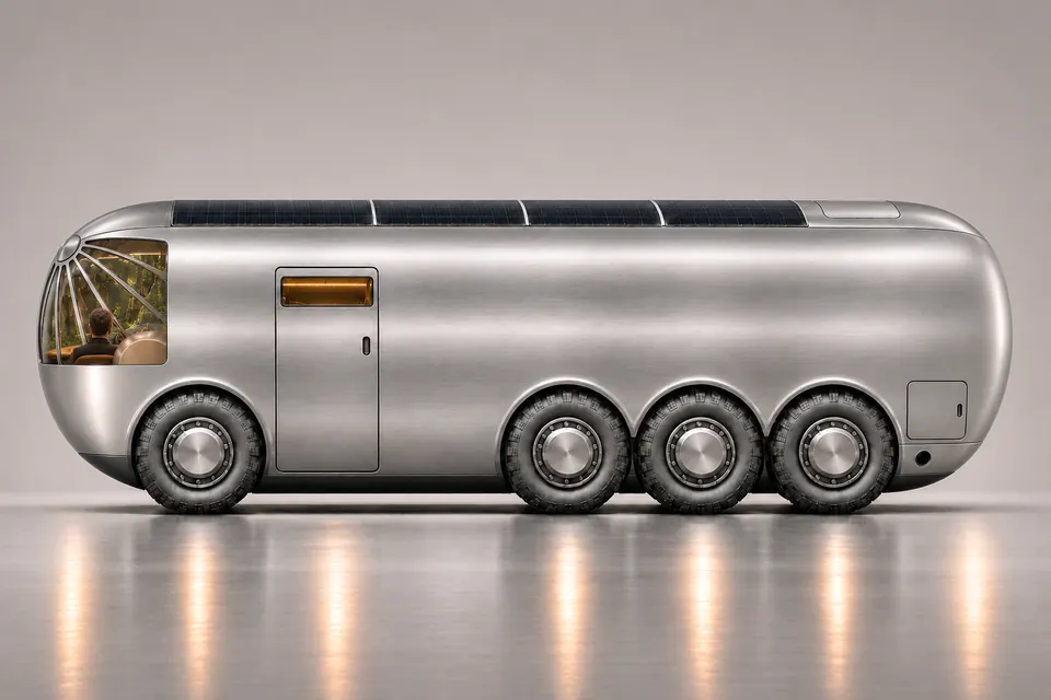
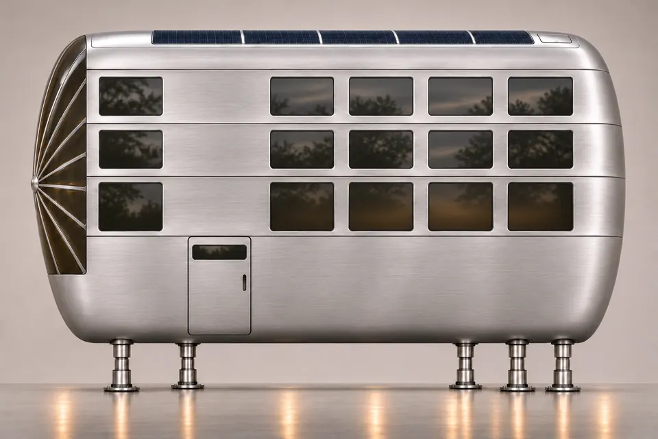
A 20-foot battery-electric capsule on eight wheels: drive low behind the front wheels, live on a deck over the tridem. It kneels to 6 ft 8 in for garages and at camp stands on its own legs and rises to 13 ft.
Concept render · AI-generated · illustrative
Views


Driving · rear seats down
Day · open floor
Night · walls closed


The outline is the centreline profile, which is also the side silhouette: each end sweeps forward and outward from a chin set back 0.30 m to a broad rounded centre at the 84.5 in crown, blended into the roof; dashed, the raised outline, whose upper half mirrors the lower about the tip. Items beside the centreline are drawn where they stand along the body (L, R and C mark the side). In the nose: the bumper beam at 16–22 in, the honeycomb block and the two crash tubes (yellow), the heat pump over them (dashed), the windscreen along the nose from 48 to 82 in (blue) and the fresh-water saddle tanks over the front housings. The low floor is 12 in up with 68.5 in over it roof down and 144.5 in raised; the deck is 49 in up with 31.5 in roof down and 107.5 in raised. Over the low floor: the chair, both doors beside it (drawn as one opening, since they are opposite each other), the leaf rack under the roof, then the toilet on the centreline with its cover up as a backrest, the shower (R) beside it, the rear seats on the side walls (L and R) and the stair (L) climbing along the left wall to the deck. Dotted are the night beds (the twin, its top 26 in over the low floor, and the flat bunk); dashed, what rises by day: the washer-dryer, which stands taller than the roof-down ceiling and so needs the raised roof, the fridge and the table. Under the deck, in 35 in of height behind the bulkhead: the fridge (left), the gray tank (centre) and the washer-dryer well (right) at the front, a flat 17 gal fresh-water tank behind them, the inverters, the battery between the tridem housings and, at the tail, the generator with the propane tank beside it.
Day · roof raised
Night · roof down


Overview
The body, chassis and roof are designed as one machine. Each side wall is framed like a bus side, carrying a cage of twelve-sided iron rib rings. The front wheels and crush zone hold the crash structure and the fresh water; the cockpit, entry, wet room and stair sit on a low floor 12 in off the road; over the rear tridem a deck 37 in higher is a crawl bunk on the road and a 9 ft room raised. Under the deck sit a ~400 kWh battery, the power electronics and a small boxed-in propane generator for parked use.
01 / Inside
Three levels in one body: a low cockpit and wet room, a telescoping stair, and a deck over the tridem that is a crawl bunk on the road and a 9 ft room raised.
Only what SKIF needs. The captain’s chair sits on the centreline behind the front wheels, with open floor on both sides of it. The right door opens right behind the right front wheel, beside the driver, onto a small vestibule; the shower stands behind it, entered from the cabin, and the toilet beside it on the centreline, directly behind the chair. Two forward-facing passenger seats fold down from the side walls behind that line, one in the shower and one in the passage; folded flat to the walls they leave the floor open. The shower closes behind a hinged two-leaf wall, the toilet under a sealed cover, and an accordion wall drawn across behind the bed makes the toilet and passage their own room. Parked with the roof down, a 36 × 78 in twin is made up across the full width over the folded seats with an end across each closed door; the left door mirrors the right, right behind the left front wheel, and either opens over the bed. Behind the bed a passage runs along the solid left wall to a telescoping stair, which extends along that wall to the deck by day and folds onto the deck when not in use. The deck covers the back of the body over the tridem: a couchbed along the right wall lies flat for the road as the 60 × 80 in mattress of a crawl-height bunk, and the galley, fridge, washer-dryer and table rise out of sealed wells in its floor only when the roof is up. Raised, it is a 9 ft room with nothing hanging from the ceiling. The battery, propane, gray tank and electronics are packed under it, sealed from the cabin. The renders are AI concepts of this layout; the plans and end views govern. In views looking aft, the vehicle’s left side is on the right of the picture.
Cockpit and rear seats: the captain’s chair sits low on the centreline on an air-ride stage and a hexapod of six stroking struts, belts built into the seat, with open floor on both sides: 68.5 in of headroom against the 58 in a 6 ft 3 in driver needs at the low setting. The two passenger seats face forward, one on each side wall behind the wet room line, their backrests on the faces of the first rear wheel housings: 18 in wide, the pan 18 in up, 37 in of legroom ahead of each pan and 63.9 in of headroom against 60. Folded, the pan swings up and the seat lies flat on its wall, 4 in thick. The right seat stands in the shower, a teak-slatted pan that is also the shower seat; the left one is in the passage beside the stair foot. They share floor with other things on purpose: the right seat folds before the shower wall can close, the left before the stair comes down or the toilet wall is drawn, and interlocks enforce it. Facing forward they need three-point belts anchored to the frame, a harder frontal-crash case than the rear-facing seats they replace.
Entry and wet room: the right door, 28 in wide and 72 in tall raised, opens beside the chair onto a 32 × 25 in vestibule. The shower stands right behind it, entered from the cabin: a 24 × 25 in pan recessed 1.5 in into the floor, 66.7 in at its centre with the roof down (a seated shower) and 142.7 in raised. A fixed wet wall runs full height along its inboard edge, and two rigid 12.65 in leaves hinged on that wall’s front end close its front, gasketed on the pan curb, the wet wall and the ceiling; open, they stack 2 in thick against the wet wall and leave a 23.3 in opening, which is also the way through to the passage, since behind the chair there are only 11.3 in. The toilet stands beside it on the centreline, directly behind the chair, side-facing left with its back on the wet wall: 19.9 in from the chair back, 68.5 in over it collapsed, 144.5 in raised, and 26.8 in of knee room across the passage (22.8 in to the folded left seat). Its hood, two nesting leaves hinged along its back, is a backrest when open; closed, it seals on a gasketed floor tray, and a UV-C LED bar and a fan through a carbon filter to the roof vent run only while it is latched, so the toilet and tray can be sanitized and washed down to the shower sump. An accordion wall of 4 in panels, stacked 5 in deep at the wet wall’s front end, draws 49.3 in along the bed’s aft edge to the left door’s aft jamb and closes the toilet, the passage and the stair foot into one room; by day it stays stacked and the floor is open.
Deck, raised: about 107.5 in over the deck, seen from over the open double-height space ahead of the deck edge, with the rail along it. The couch is 80 in long, two seat cushions, about two thirds of the 117.6 in deck. The galley rises out of the floor to 36 in along the left wall and the table in front of the couch; lowered, each lid is a flush deck panel on a gasket. Under the front of the raised galley the fridge comes up too, its drawers facing the stairhead; on the road it waits low behind the bulkhead with its drawers to the low floor. At the front right the washer-dryer rises out of its well, its door facing forward over the deck edge at chest height for someone standing on the low floor; it needs the raised roof.
The first view cuts the front wheels at 0.65 m, where the footwell begins between the fresh-water tanks over the housings, with the crash stack ahead of it: the beam, the honeycomb block and the two tubes, the heat pump above. The low floor has 68.5 in at the centreline while driving and 144.5 in raised. The cockpit view shows the chair at its low setting with open floor on both sides, the right door with its gull-wing leaf beside it and, dotted, the crosswise twin over them, its mattress top 26 in up with 42.5 in over it at the centreline and 33 in at the walls, into the recesses in both door leaves. The third view, at 2.65 m, cuts the wet room ahead of the tridem: the shower at the right, off the centreline over a pan recessed 1.5 in into the floor, with 66.7 in at its centre (69.3 in at its inboard edge), a seated shower with the roof down, behind the fixed wet wall, with the right seat folded on its outer wall; the toilet on the centreline with its cover up as a backrest; and the stair extended along the solid left wall, 4 in off it where the left seat folds, with the grab bar at its foot. The fourth, at 3.10 m, cuts the deck front between the first tridem housings: the fridge, the gray tank and the washer-dryer under the deck and the folded stair on the landing above. The deck has 31.5 in while driving, with the couchbed lying flat as the bunk mattress and 25.5 in over it, and 107.5 in raised. Under the deck, 35 in of height between the housings holds the battery.
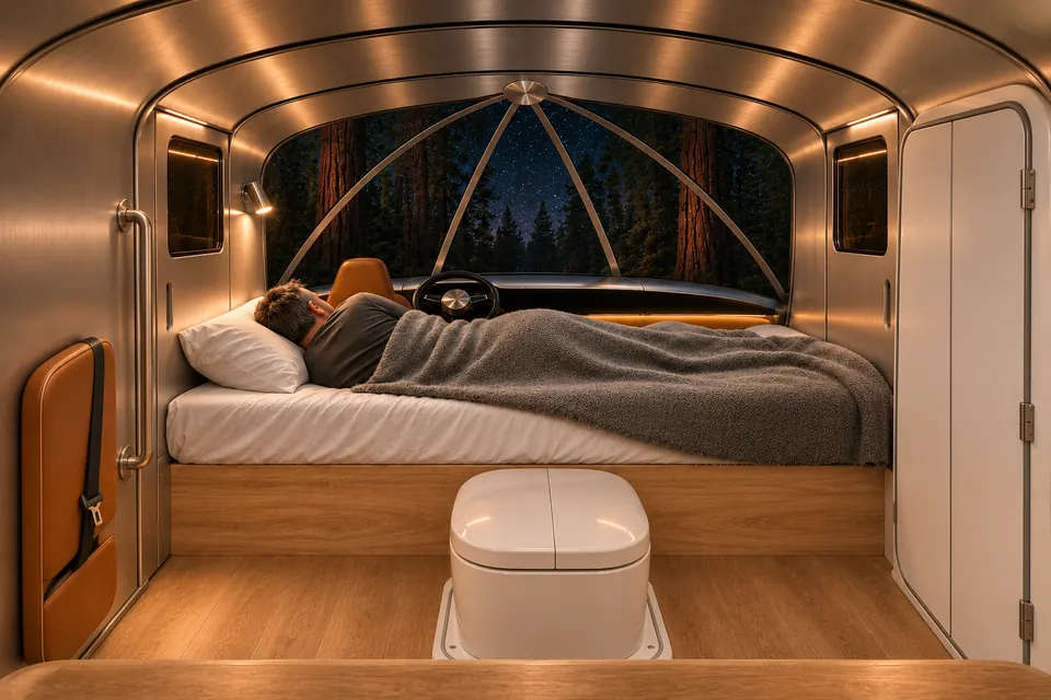
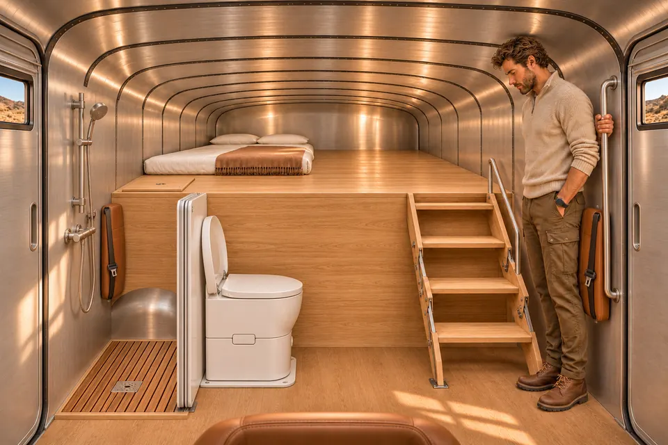
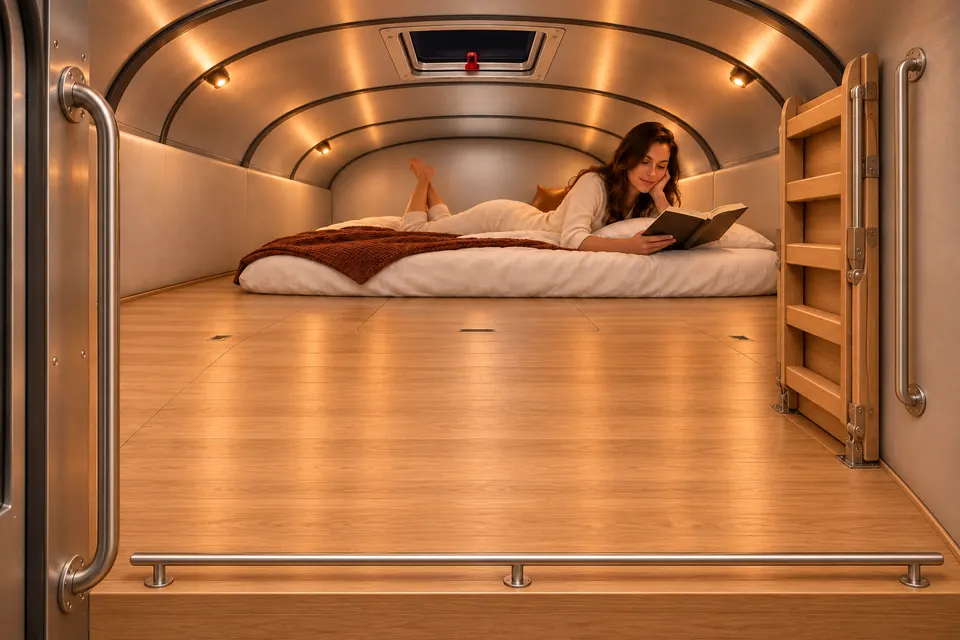
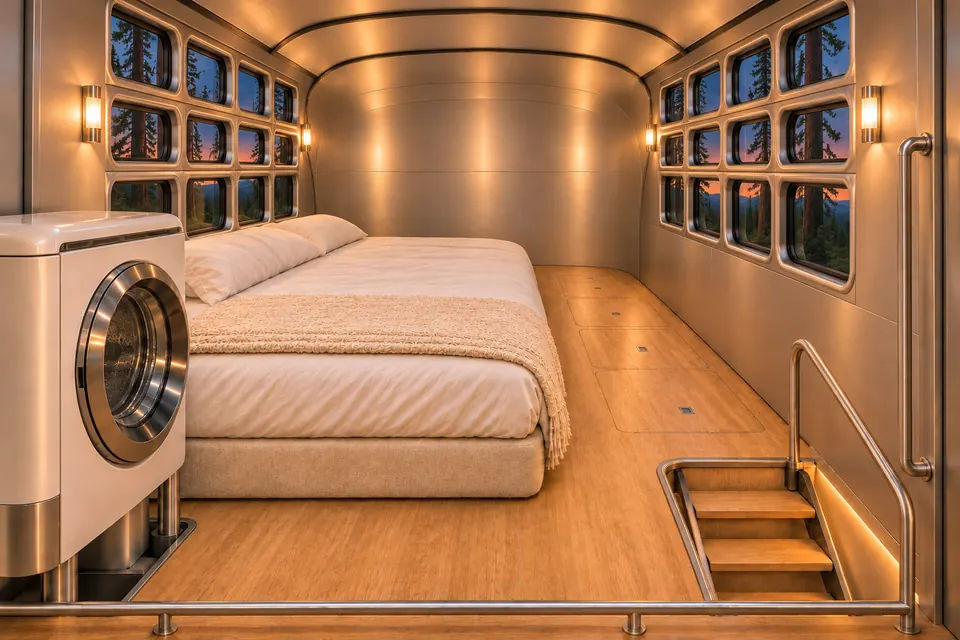
02 / Park and rise
Parked, four telescoping corner legs take the weight, the eight wheels draw up inside and curved panels close the arches. Then four synchronized corner masts lift the roof cap 76 inches on three nested wall bands inside a smooth outer fairing. Mechanical locks carry the load at every stage.
 1Stand and retract
Park level with wind below the 10 m/s lifting limit. Four corner legs extend onto broad pads and take the load, each wheel draws up on its suspension arms, and curved closures slide shut over the arches.
 2Release and lift
Road locks release in sequence. One geared drive turns four mechanically synchronized corner winches; every stage has an automatic anti-drop catch.
 3Lock and brace
Shear keys lock each stage at full height. Tensioned X-braces stiffen the walls and roof. If power fails, the locks still hold the roof.
A concept, outside the budget
The legs and wheel closures carry the SKIF and Habitat wheel-closure idea (design note jacks and wheel closure) to the 50K. The mass budget holds only four stabilizers at 551 lb. Full-weight legs and their hard points on the lower chords, the wheel lift and closures at four axle stations all need their own engineering at 50,000 lb. The only screen so far is the wall itself. Raised on four corner legs, the lower chord reaches 64 of 75 MPa, and at each door, where the lower chord and the seam rail are both cut, the sill beam alone carries the bay: 165 of 250 MPa at each door. Both walls pass, so four corner legs are the stance; a pair at 2.20 m, in the aft jambs of both doors, would bring the sill beams to 35 MPa and the chord to 36. Legs, lift and closures are not sized or weighed yet.

Raised, the deck becomes a 9 ft room the full width of the body, standing on its legs with the wheels hidden; on the road its furniture folds flat into a crawl bunk, and the cockpit, wet room and stair keep 68.5 in over the low floor.
03 / Frame
Each side wall is a framed girder, the way a bus side is built. A lower chord of hollow electroformed iron box vertebrae, clamped together by steel strand, runs nose to tail just above the tires; an upper chord runs along the roof edge; posts at the rib rings join them, and solid panels close the lower walls everywhere except one door in each, right behind the front wheel housing. The rib rings hang from the walls, so nothing structural crosses the floor.

The lower chord of each wall: 150 × 180 mm with 12 mm walls, 500 mm long, post-tensioned by steel strand. A bought steel box is the fallback if the thick iron does not qualify.

Deep iron frames drop from each lower chord around the tires and carry the wishbones and dampers. Together with the rib rings and the floor tub they have to close the body into a torsion box.
Driving, shear keys at every post lock the roof cap down, so the lower and upper chords work together about 26 in apart. Each wall carries half of 50,000 lb on spring supports at the four axles, at 2.5 times weight, with a light and an even nose: worst case 100.9 kN·m and 92.3 kN of shear. Taking no credit for the solid panels, the iron lower chord reaches 52 of its 75 MPa limit and the steel upper chord 91 of 250; with the panels working as shear webs, 21 and 34. Each wall has one door, 28 in, and the two are opposite each other at 1.44–2.15 m, right behind the front wheel housings, where the hood loads come in. Each cuts the lower chord and the seam rail, and a portal of a 300 × 150 × 12 mm sill beam, two 0.10 m box jambs and the upper chord carries the bay: 72.7 kN·m and 62.6 kN in each wall, sill 35, over the door 41 and jambs 74 of 250 MPa. Parked on the four corner legs the sill beam carries each bay alone at 165 of 250 MPa, with the lower chord at 64 of 75, so both walls can take their door; a leg pair in the aft jambs at 2.20 m would bring the sills to 35.
A hood that crushes
The first 0.64 m of the nose, behind its rounded skin, is a staged crush stack: a 100 × 150 × 6 mm steel bumper beam 1.4 m wide at 16–22 in, a car’s bumper height, curved in plan to follow the skin, its face 0.17 m behind the nose tip; 0.13 m of aluminium honeycomb that crushes first at about 2.3 MN (10 g); then two 250 mm square steel crash tubes with 16.8 mm walls, 7 in either side of the centreline, crushing 0.26 m at about 6.8 MN (31 g). About 268 lb in all. Behind it the lower-chord segments ahead of the cockpit are made to fold, and the heavy modules under the deck sit on load-limiting mounts behind a bulkhead. As a sizing estimate only, not a crash simulation: stopping 50,000 lb from 30 mph against a rigid barrier is 2.04 MJ, which this stack absorbs in 0.39 m, 23.8 g on average against 20.4 g in the 0.45 m of the flat-nosed design; the rounded nose sets the beam back and costs that crush length. Behind that pulse, mounts that hold the 3,636 kg pack to 15 g need about 0.27 m of stroke, more room than the inverters and pop-up wells ahead of the pack leave today. The captain’s chair rides on a hexapod of six stroking struts over its air-ride stage, after crashworthy helicopter seats, which limit the load to about 14.5 g times the occupant and seat mass: sized for 15 g (about 20 kN) frontal over 0.15 m of seat travel, 92 mm of strut stroke, it holds that limit up to about 24 mph into a rigid barrier; at 30 mph it needs 0.27 m or a 19.3 g limit. Vertically it allows 14.5 g over 0.15 m, sideways 10 g over ±0.10 m, and its end stops take the FMVSS 207/210 seat and belt loads, about 34 kN. Posts, joints, shear keys, twist, suspension hard points and side loads are not checked.
The first 0.53 m of the nose is a staged crush stack: a 100 × 150 × 6 mm steel bumper beam 1.6 m wide at 16–22 in, a car’s bumper height; 0.15 m of aluminium honeycomb that crushes first at about 1.9 MN (9 g); then four 200 mm square steel crash tubes with 10.6 mm walls, 8 and 26 in either side of the centreline, crushing 0.30 m at about 5.8 MN (26 g). About 312 lb in all. Behind it the lower-chord segments ahead of the cockpit are made to fold, and the heavy modules under the deck sit on load-limiting mounts behind a bulkhead. As a sizing estimate only, not a crash simulation: stopping 50,000 lb from 30 mph against a rigid barrier is 2.04 MJ, which this stack absorbs in 0.45 m; behind that pulse, mounts that hold the 2,848 kg pack to 15 g need about 0.22 m of stroke, more room than the inverters and pop-up wells ahead of the pack leave today. The captain’s chair rides on a hexapod of six stroking struts over its air-ride stage, after crashworthy helicopter seats, which limit the load to about 14.5 g times the occupant and seat mass: sized for 15 g (about 20 kN) frontal over 0.15 m of seat travel, 92 mm of strut stroke, it holds that limit up to about 25 mph into a rigid barrier; at 30 mph it needs 0.22 m or a 17.5 g limit. Vertically it allows 14.5 g over 0.15 m, sideways 10 g over ±0.10 m, and its end stops take the FMVSS 207/210 seat and belt loads, about 34 kN. Posts, joints, shear keys, twist, suspension hard points and side loads are not checked.
The nose and the front wheel housings either side of the footwell are packed with light and dense things: the crash structure with the heat pump’s outdoor unit over it, the front axle’s housings and steering, 53 of the 70 gal of fresh water in saddle tanks over the housings whose tops follow the driver’s sightline (the other 17 gal lie in a flat tank under the deck front), the pump and filters and the 12 V electronics in the dash. Full, the steered axle carries about 12,180 lb, 26.1% of the weight and 69% of its tires’ rating; with both fresh tanks empty, 25.5%. The tridem tires run at 77%.
04 / Running gear
One steered axle right behind the nose and a tridem of three axles at the back, 1.025 m apart, set 0.09 m forward so the last one clears the undercut tail. The front axle steers and the last tridem axle counter-steers to tighten the turn. The rear four wheels are driven by four electric motors through portal gear cases, so no shafts cross the floor.
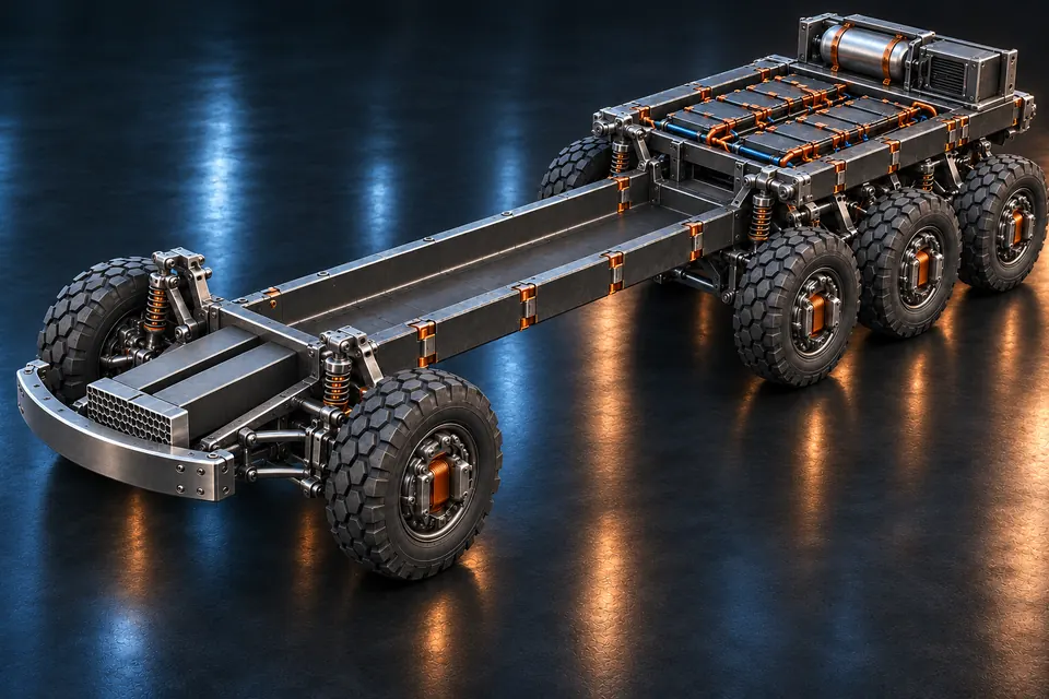

The earlier baseline: a used ISB/B6.7-class diesel of about 300 hp, an Allison automatic, differentials and shafts to the portals. It needs a machinery block and shaft corridors that would cut into the clear aisle, so it was dropped for the low-aisle layout.
A ~400 kWh battery under the deck feeds four rear traction motors on the portal inputs; a 5.5 kW propane generator is a backup, not a range extender. About 127 kW holds 70 mph on level road; 55 mph up a 6% grade needs about 470 kW, so the motors and inverters have to be sized for that. Used motor-inverter assemblies are listed from $2,195 each, before reductions, cooling and controls.

Ride height adjusts as it drives: 4 in under the floor tub at walking pace under height limits, which puts the crown at 79.5 in; 9 in on the road; more on rough tracks. Kneeling uses 5 of the 5.9 in of bump travel, so it is for walking pace only, and the approach angle drops from about 29° to 12°. This is a road-and-gravel vehicle, not a rock crawler; travel, tire and axle ratings are reserved but not yet selected or tested.
05 / Ribs and skin
Every half metre, a ring of twelve straight electroformed iron segments meets at keyed knuckle joints, the same joint language as the vertebrae. The rings hang from the framed side walls, a low floor tub closes their bottoms, and curved battens fill the corners so the skin is one smooth curve.

Insulation and an oak lining fill the inside of each rib. Outside, crescent spacers and curved battens carry the skin across the polygon’s corners, so no facet shows.
Four corner telescopic masts with three sections each, each with at least 10 kN of working lift after reeving losses. Mechanical catches stop each stage if a line fails. In camp mode, 8 kN X-braces in the walls and roof take the wind.
Battery under the deck Fresh water in the hood Propane tank and generator at the tail
The heavy items sit low: the battery between the tridem housings under the deck, the propane gear at the tail, 53 gal of fresh water in the hood. In a rough estimate the steered axle carries about 12,180 lb, 26.1% of the weight and 69% of its tires’ rating, and the tridem 34,410 lb, 78%; the water in the hood adds about 440 lb to the front axle. The CG sits about 31.7 in above the ground, roughly 3 in lower than the central-seat layout of 2 November. Moving walls carry only light panels.
06 / Inside, in detail
Driving, the low floor is 12 in off the ground at ride height and the ceiling 68.5 in above it at the centreline, so the cockpit, passage and toilet have standing room with a slight stoop; the deck is 37 in higher, a crawl bunk on the road and a 9 ft room raised. The widths are set by the wheels: the front axle steers inside its housings and the tridem housings bound the space under the deck.
07 / Power and stores
About 400 kWh of LFP fills the space under the deck between the tridem housings, with the power electronics at its front and the propane gear at the tail. It drives the four rear motors, takes back braking energy on the way down and runs the house. It charges at truck DC fast chargers, on AC hookups and a little from roof solar; parked, a small boxed-in propane generator runs the house and can top the pack up.
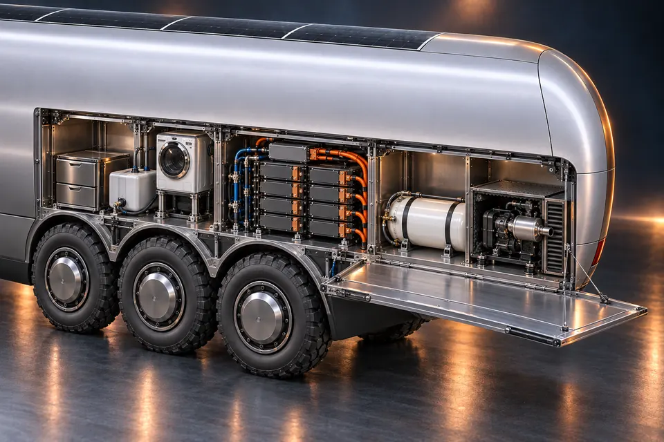
Budgeted, not weighed: 46,589 lb allocated with everything aboard, the water and propane tanks full and a 2,205 lb growth allowance, leaving 3,411 lb of the 50,000 lb ceiling unallocated.
| Item | Pounds |
|---|---|
| Wheel ends, tires, brakes, portals | 8,818 |
| Traction and house LFP, ~400 kWh | 8,017 |
| Ribs, floor, shells, roof and lift | 5,050 |
| Framed side walls: chords, seam rails, posts, tendons | 4,200 |
| People, food, tools, spares, cargo | 3,527 |
| Suspension, steering and rear steer (no shaft credit taken) | 3,367 |
| Interior, insulation, HVAC, plumbing | 3,086 |
| Construction-growth allowance | 2,205 |
| Protection and RF package | 1,808 |
| High deck, bulkhead, crash structure, nose end screen, two doors, crash mounts | 1,450 |
| Propane generator in its acoustic enclosure, tank full, furnace, compartments | 816 |
| Water, all 88 gal full | 734 |
| Four rear traction motors and inverters | 690 |
| Inverters, chargers, wiring | 661 |
| Empty tanks and restraints | 551 |
| Four stabilizers | 551 |
| Deck: couchbed, galley, fridge, washer-dryer lift, table | 423 |
| Cockpit: hexapod chair, crosswise twin, rear seats, wet room, stair, grab bar | 335 |
| DC fast-charge inlet, HV junction, pack cooling | 300 |
08 / How it’s built
The bulk structure is electroformed in-house. Strand, anchors, bearings, gears, brakes, battery modules, motors and the electrical gear are bought.
 1Grow the parts
Box vertebrae, end plates, housing frames and ribs are electroformed in iron on reusable mandrels.
 2Stack the lower chords
Twelve box vertebrae per side line up on a roller jig with their keyed faces meshed; steel strand is threaded through the ducts.
 3Tension the strand
A multi-strand jack draws each chord’s strand to its preload, and wedge anchors lock the ends.
 4Make it roll
Housing frames, wishbones, coil-overs, portal wheel-ends, motors, steering and brakes hang from the two lower chords: one steered axle at the front and the tridem at the back.
 5Raise the ribcage
Twelve-sided rib rings with keyed corner joints bolt to both lower chords and close the low floor tub; seam rails, posts and the upper chords turn each side into a framed wall, and the deck frame spans the tridem.
 6Install the systems
The battery, power electronics and the sealed wells for the fridge, the washer-dryer and the pop-up galley go in under the deck between the tridem housings, the propane tank and the generator in its acoustic enclosure into sealed compartments at the tail, the fresh water into saddle tanks over the front axle and a flat tank under the deck front, and the heat pump into the nose.
 7Close the skin
Nested wall bands, corner masts and curved battens go on, the smooth skin closes over the ribs, a door goes into each side right behind the front wheel housing, and the fan windscreen goes into the rounded fixed nose, above the crash stack and under the hub at its tip.
 8Prove it
Weigh every corner, test brakes and steering, cycle the roof and the wheel lift, and qualify the structure before any road use.
09 / Specifications
Status
These are design allocations and analytical screens, not a rated, registered or tested vehicle. Nothing is inherited from a donor truck.
Images on this page are AI-generated concept renders made from text prompts. They show the intended look; the dimensions in the drawing and tables govern. Prices are dated published references or editable assumptions, not quotes.